Personal Protective Grounding
Revised March 2026
Purpose
The PRIMARY function of personal protective grounds is to provide maximum safety for our employees while they are working on de-energized lines or equipment. This will be accomplished by making provisions that will reduce the potential voltage differences at the worksite (voltage across the person) to a safe value in case the equipment or line being worked on is accidentally energized from any possible source.
The SECONDARY function is to protect against induced voltage from adjacent parallel energized lines.
The THIRD function is to make the protective devices (relays, circuit breakers or fuses) disconnect the energizing source within a given time/current relationship.
EQUIPOTENTIAL ZONE (EPZ) Temporary protective grounds shall be placed at such locations and arranged in such a manner as to prevent each employee from being exposed to hazardous differences in the electrical potential.
Applicability
Personal Protective Grounding applies to all District employees working under the scope and application of WAC 296-45 Electric Power Generation, Transmission, and Distribution .
This section is intended to be used in conjunction with WAC 296-45, the District’s Switching and Clearance Procedures, and the T & D Guidelines.
Grounding Equipment
Grounding equipment shall be of approved current-carrying capacity capable of accommodating the maximum fault current to which the line or equipment could be subjected. Protective grounds shall only be used for grounding. Personal protective grounds will be tested annually.
Grounding jumpers shall have approved ferrules and grounding clamps that provide mechanical support for jumper cables independent of the electrical connection.
Protective grounds shall have an impedance low enough to cause immediate operation of protective devices in case of accidental energizing of the line or equipment.
Personal Protective Grounds
For Personal Protective Ground sizes used at the District see Personal Protective Grounds. Personal Protective Ground size documentation is maintained by the System Planning and Protection team.
Attaching and Removing Ground(s)
Grounding equipment shall be given a visual inspection, and all mechanical connections shall be checked for tightness before each use. Protective grounds shall only be used for grounding.
The surface to which the ground is attached shall be clean before the ground clamp is installed; otherwise, a self-cleaning clamp shall be used.
When attaching ground(s), the ground end shall be firmly attached first to a reliable ground with the other end attached to the line or equipment by means of an approved live line tool.
When a ground is removed, the grounding device shall be removed from the line or equipment using a live line tool before the ground end connection is removed.
Grounds may be temporarily removed, when necessary, for testing purposes. During a test procedure, the lead worker shall ensure each employee uses insulating equipment and is isolated from hazards and shall institute any additional measures necessary to protect each exposed employee until the grounds are reinstalled.
When the conductor separation at any pole or structure is so great as to make it impractical to apply shorts on all conductors, and where only one conductor is to be worked on, only the conductor to be worked on needs to be grounded.
In cases where ground rods or pole grounds are utilized for personal protective grounding, personnel working on the ground should maintain a sufficient distance from such equipment or utilize other approved procedures designed to prevent touch and step potential hazards.
Caution must be taken if the de-energized line to be worked on is parallel to an energized transmission line. Induced voltages and circulating currents may be substantial enough to cause injury or death.
Personal Protective Grounding of Overhead Distribution Lines
STEP ACTION
- Identify and isolate the line. Obtain visible openings on the source side (and the load side, if possible) of the line or equipment.
- Call ECC for a clearance. (Follow clearance guidelines outlined in the District’s Switching and Clearance Procedures manual.)
- Use an approved voltage detector to test the line or equipment to ensure it is de-energized.
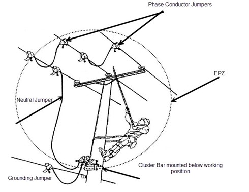
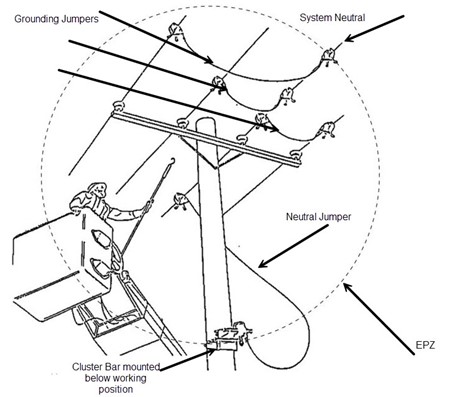
- Make grounding connections in the following order:
- Install a cluster bar on the pole just below the work area. Leave adequate working space above it.
- Clamp one end of a 4 foot. jumper to the cluster bar, and the other end to the common neutral.
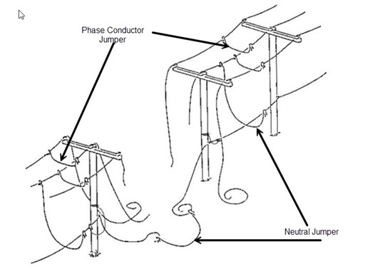
- Jumper from the cluster bar to the closest phase conductor. Jumper the other phases together, working from the nearest to the farthest away.
- Remove the grounds in the reverse order of installation.
If there is a possibility the employee may come into contact with any part of the structure (pole, cross arm, line hardware, grounding jumpers, etc.), personal protective grounds shall be installed. Employees working out of an insulated platform are not exempt from this rule.
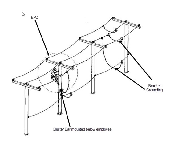
If it is preferred to use a set of bracket grounds, as shown above, line workers shall install personal protective grounding on the structure they will be working on. Install a jumper from the cluster bar to the primary phase being worked. When work moves to another phase on the same pole, move the jumper to the new phase and begin work.
CAUTION: If the de-energized line to be worked is parallel to an energized HV transmission line, an induced voltage may be present. If the line worker uses a set of bracket grounds and a set of personal protective grounds, a circulating current may be present between the two sets of grounds.
The amount of induced voltage and circulating current depends on the voltage on the energized HV transmission line, how close the energized line is to the de-energized line, the distance the two lines parallel each other, and the distance between the two sets of grounds.
Always use an approved live line tool to install/remove all ground jumpers on the phase conductors to be grounded.
DANGER!
WHERE WORK ON DE-ENERGIZED AND GROUNDED LINES AND EQUIPMENT CANNOT BE DONE WITHIN THE EQUIPOTENTIAL ZONE (EPZ), APPROVED RUBBER GLOVES SHALL BE WORN.
STEP ACTION
- Identify and isolate the line. Obtain visible openings on the source side (and the load side if possible) of the line or equipment.
- Call ECC for a clearance. (Follow clearance guidelines outlined in the District’s Switching and Clearance Procedures manual.)
- Use an approved voltage detector to test the line or equipment to ensure it is de-energized.
- Install personal protective grounds on both sides of the worksite at the nearest location where the primary and neutral conductors are in their normal positions, and where the grounds will not interfere with the work.
Note: Touch potential hazards refer to the difference in voltage measured between the grounding equipment and a worker in contact with the grounding equipment at the time it is accidentally energized. Step potential hazards refers to the difference in voltage measured between the feet of the worker standing or walking in an electrical field created by high voltage being brought to earth.
Additional Requirements for Underground
Before cutting into a high-voltage cable or opening a high-voltage splice, the cable shall be de-energized, a clearance obtained, tagged, tested with an approved testing device, and then grounded in an approved manner. If in an area where a high voltage cable or splice is to be cut and the ground cannot visibly be seen, the high voltage cable or splice shall be identified, tested, and spiked before work is performed.
A capacitance charge can remain in high-voltage cables after it has been disconnected from the circuit and a static-type arc can occur when grounds are applied to such cables.
When work is to be done on cables or equipment in a high voltage underground system, precautions to prevent back feed shall be taken. This shall include either isolating or grounding the secondary conductors.
When work is performed on a cable at a location remote from the cable terminal, the cable may not be grounded at the cable terminal if there is a possibility of hazardous transfer of potential should a fault occur. If the cable(s) cannot be isolated and are grounded at a remote location from the work area, an equal potential grounding blanket must be used to protect the employee performing the work.
For more detailed information for grounding different types of underground equipment see T&D Guidelines, 4-20-5.0.
Vehicle Grounding
See Vehicle and Equipment Grounding section of this manual.
Training and Resources
Trainings on Grounding can be assigned to employees’ Learning Plans in Learning Central.